DIY Smartwatch
Motivation
The pinnacle of microcontroller lab I attended this semester is my own project based on any microcontroller I could get my hands on. I thought hard about things that are cool but also useful, things which will not end up at the bottom of my drawer. Recently gathering data has been my jam, and this has led me to the idea of a smartwatch. I figured a gizmo measuring my heartbeat and saturation is a good starter and the rest will come later.
Construction
Hardware
I set off in search of parts and quickly found what I needed. Waveshare provided me with more than what I wanted: Waveshare RP2040 Touch LCD 1.28”. This is a touch-enabled round display integrated with RP2040 microcontroller, accelerometer+gyroscope module, RTC and battery header. Almost fully-featured smartwatch in itself, and to be honest I feel quite dirty using it in my project, but due to time, money and volume constraints this is the best decision.
Arguably, one might complain that the board has no connectivity, thus why the first draft included ESP32 which would talk to RP2040 through exposed GPIO ports. However, because of coming deadline and various difficulties with that soution, the idea was dropped (for now).
From the beginning the most important part besides the chip and screen was pulse oximeter. I reviewed all available options which did not cost a small fortune and settled for MAX30102 board from local eshop. This model does not contain green LED (like in MAX30105). Green light makes for better wrist measurements, but I could not find any such modules and just hoped for luck.
At this point my sole concern has been battery dimensions. I found Li-Pol Akyga 85 mAh 1S 3,7 V which might just barely fit in what I had in mind.
Code
I started by writing some basic program to show date and time. As time has been critical factor I decided to use MicroPython for the first time. Sites around the web adviced me to use Thonny IDE, so I complied. I plugged my RP2040 touch screen board with BOOT button pressed and in a matter of seconds I could flash MicroPython right away. Pretty simple.
The first thing I did was copy the example code from Waveshare and strip it off the demo functionality. This way I obtained a neat driver for my board which I placed in separate file. My next step was date and time - it turns out the whole deal is done in a few lines of MicroPython:
from machine import RTC
import time

...

rtc = RTC()

def draw_ui(LCD):
    t = time.localtime()
    time_string = str(t[3])+':'+'{:02d}'.format(t[4])+':'+'{:02d}'.format(t[5])
    LCD.fill(0)
    LCD.write_text(time_string, 25, 105, 3, 65535)
    date_string = str(t[0])+'-'+'{:02d}'.format(t[1])+'-'+'{:02d}'.format(t[2])
    LCD.write_text(date_string, 40, 140, 2, 65535)
    LCD.show()

while True:
    draw_ui(LCD)

LCD.fill(0)
LCD.show()
To me that short time necessary to get something to work was astonishing. Here I was holding a working watch done in five minutes. Happy with the result I eagerly started to give my code some structure. In the following steps I added panels which you can swipe up and down along with arrows showing whether there are more panels to swipe to. I tried to incorporate LVGL Python bindings to make nicer visuals, but my efforts went in vain, so I prioritized quick progress over doing things elegantly.
The biggest challenge was to utilize the pulse oximeter. There is a library called MAX30102-MicroPython-driver, but it has no ready example of \(SpO_2\) measurement. I searched for some other solutions like MAX30105 drivers and even thought about running C pulse oximeter code on one core and MicroPython interface on the other, but in the end I settled for MAX30102-MicroPython-driver with modified example code. The modified parts were pin definitions, red LED measurement logging and some sampling rate values. I also added saturation measurement as follows:
R = sum(red_peaks[:][0]) / sum(ir_peaks[:][0]) * len(ir_peaks[:][0]) / len(red_peaks[:][0])
spo2 = 100 - 5 * R
Where red_peaks and ir_peaks are lists generated by peak finding function.
The last functionality I added to my firmware was level bubble. It is just a circle placed at scaled X and Y output of onboard accelerometer.
The whole code is available in my repository.
Pinout
There is not much to say about pinout. I connected the MAX30102’s SDA to pin 26 and SCL to pin 27 of Waveshare board, although any GPIO pin pair would be ok after slight code change.
Case
I settled for 3D printed model of my making. It is made of PLA with 0,4 mm nozzle (available at my faculty). Fits very tightly.
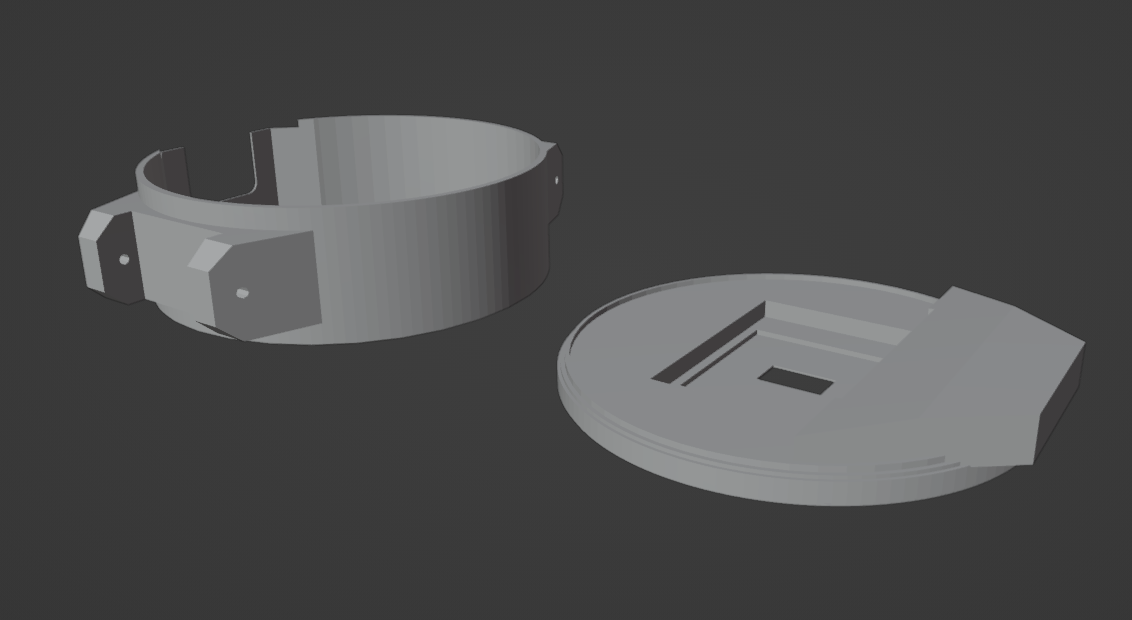
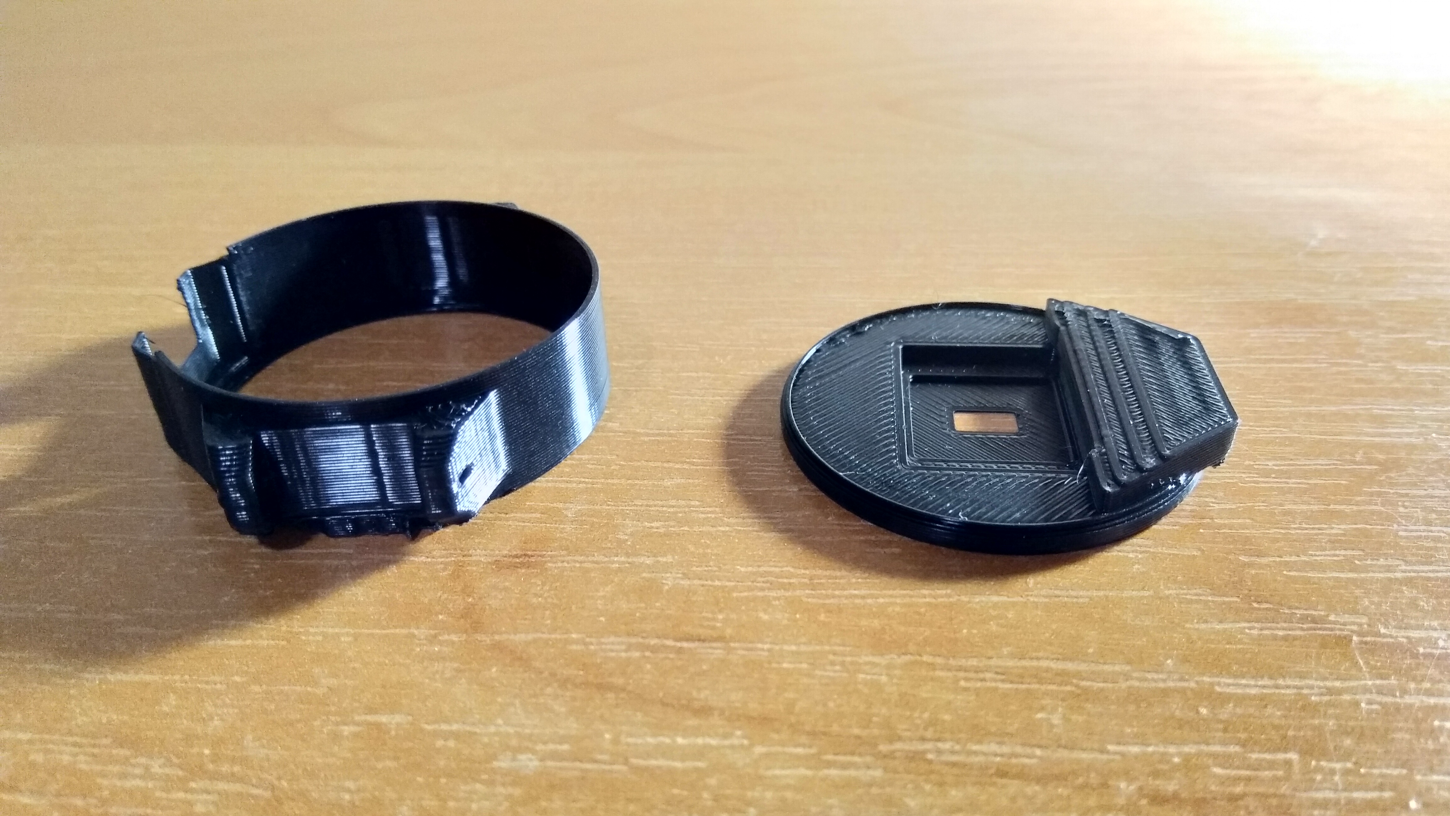
At the time of writing the case is too short to fit all cables; this will be repaired as last-minute effort before deadline, the student way.
Closing remarks
The case needs some polishing when it comes to housing all the stuff, but overall effect is quite satisfactory for a project done in about one week. Sometimes the MicroPython code crashes, probably something related to pulse oximeter thread, but I had no time to repair it yet. For me this is, first and foremost, a platform to test new ideas and as such it suits its purpose well.
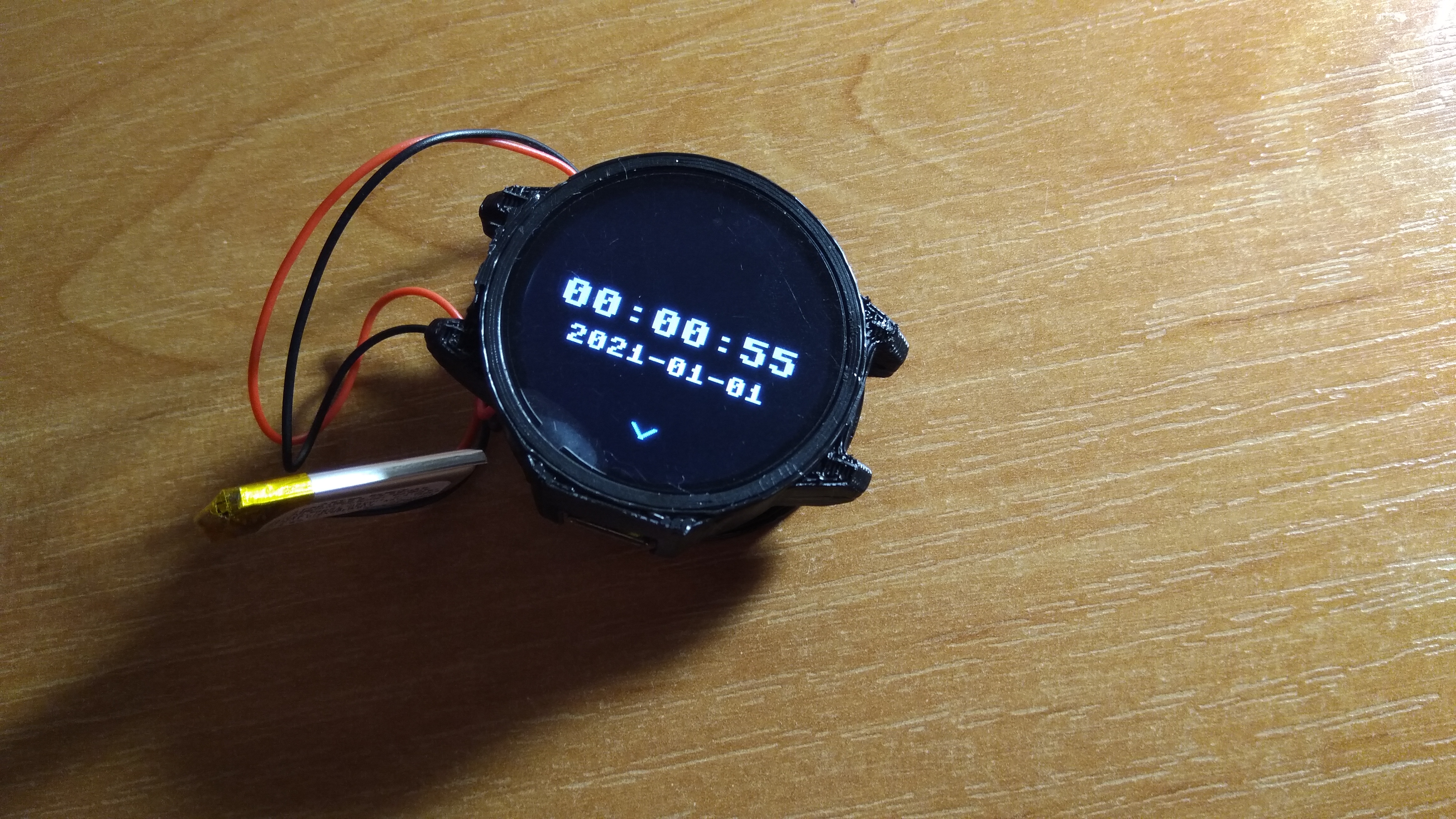
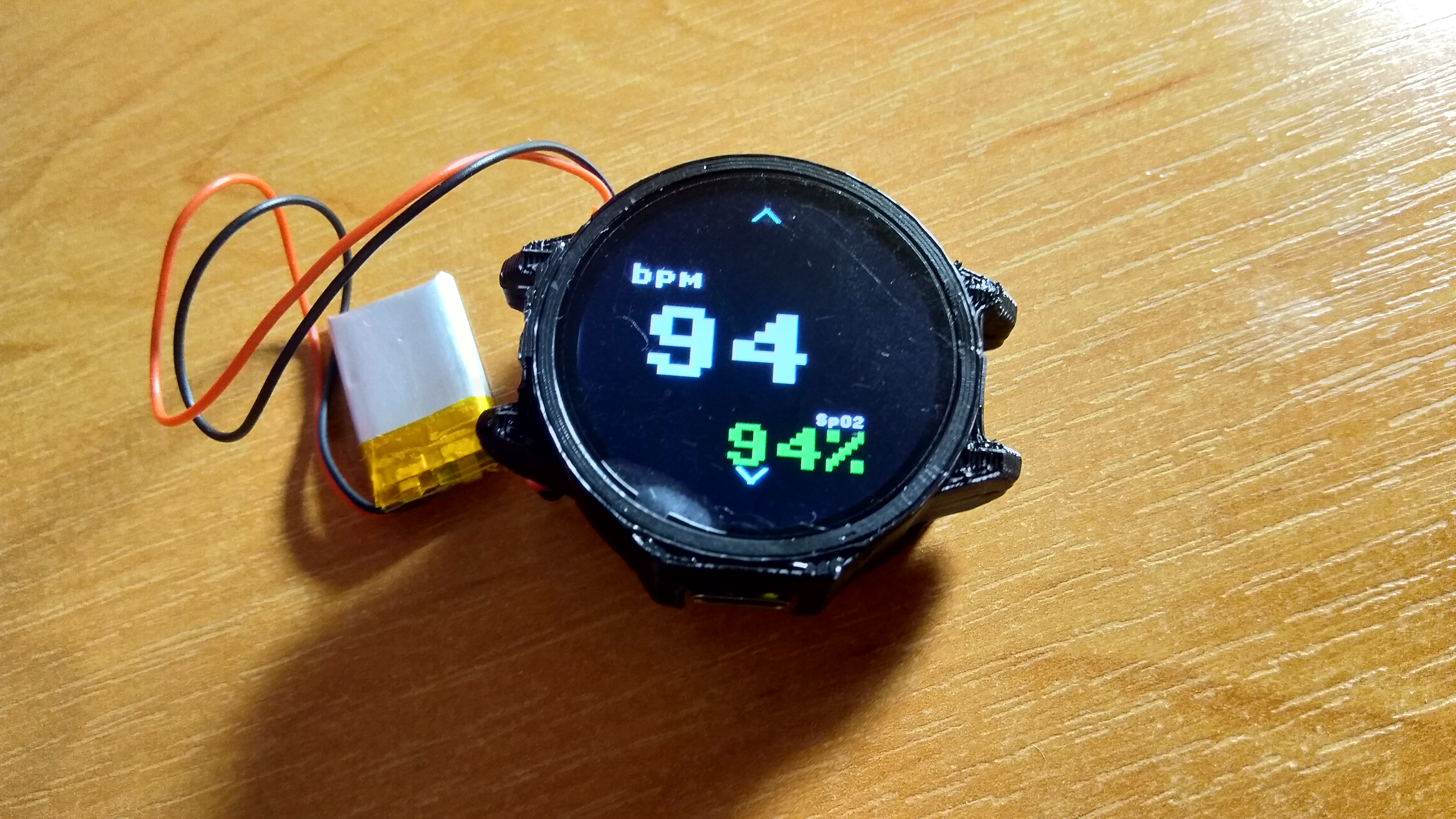
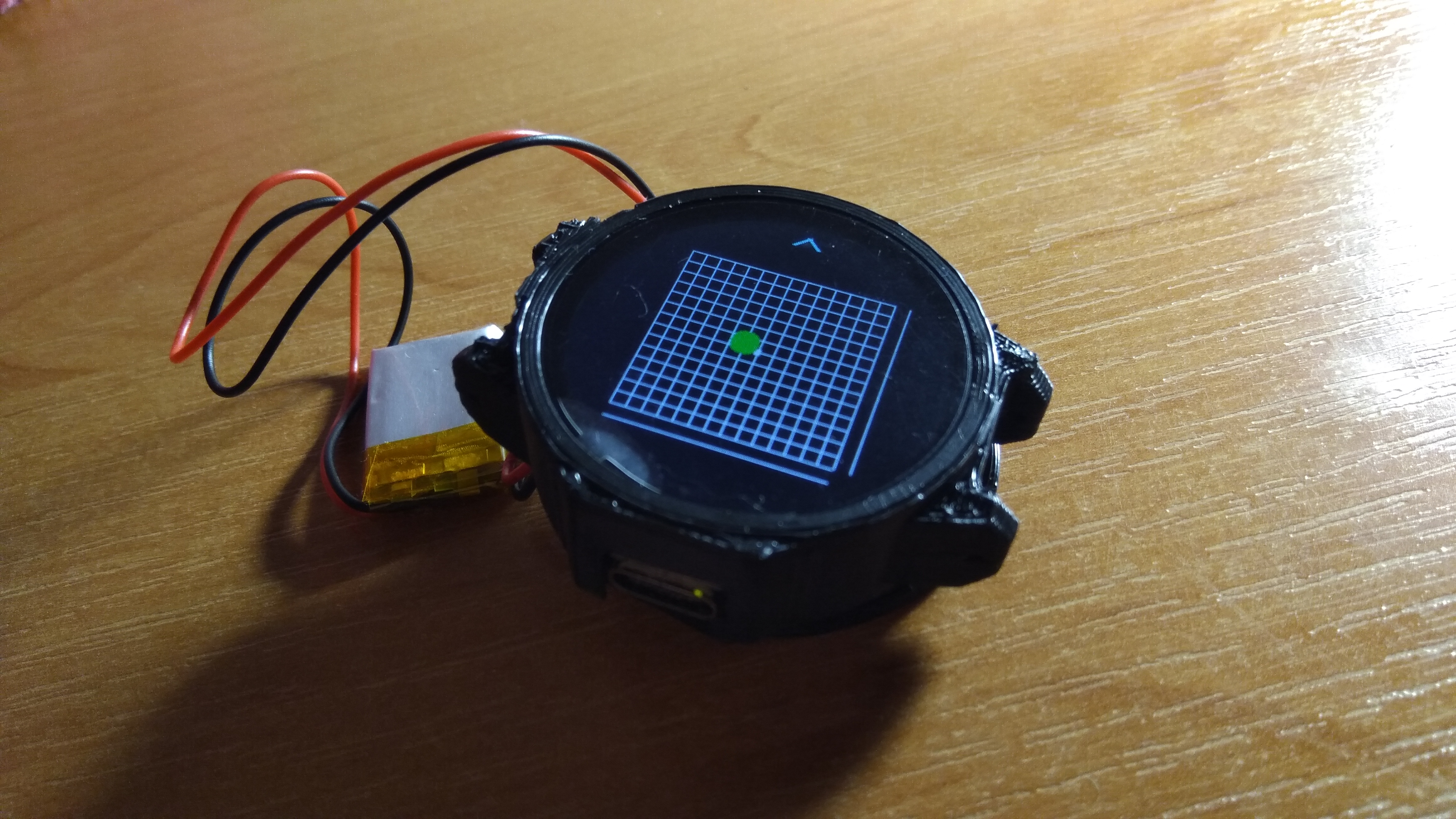
Things to do later: install straps, print more precisely, fix buggy code, add more software features, add a way to turn this thing off (shhh!).